

To achieve high production efficiency and throughput it is important to have an optimized production flow system. Designing a production line is complex and can be time-consuming. When designing a single conveyor or a complete production line, an easy-to-use design tool helps to simplify tasks, reduce engineering error and make communication straightforward.
An intelligent way to design and get an overview
There are many different steps involved in the process of designing and implementing a new conveyor or production line. An effective design process, therefore, plays a major role to achieve a satisfactory result. A design tool that easily and quickly allows you to design a new line saves you both time and money. A production line design tool should permit to embed the factory’s CAD layout and measurements right from the start so you can design the production flow according to this. This provides a great overview. It is also beneficial for engineers if he or she can visualize and simulate the movement of products in a production line before it is ordered. In that way, it is possible to analyze the outcome and prevent potential bottlenecks and errors in the production line prior to the implementation.
Embedded guidelines reduce engineering errors
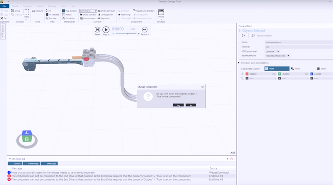
The best design tools offer built-in engineering guidelines and each component has its own intelligence, making it easy for also non-engineers to make advanced use of the tool. Depending on the choices you make, the tool can recommend changes, improvements or additions to make the production line as optimized and effective as possible. It eliminates the risk of errors and ensures that nothing is missed. If you, for example, design an s-shaped conveyor line with a particular horizontal angle, the tool will automatically choose the correct component, hindering you to choose a radius of the bend that is not possible.
Compatibility with other tools
Modern design tools are fully compatible with other tools. Generation of CAD and STEP/SAT files are basic features which allow the users to continue the work in CAD tools or share the drawings with suppliers. Better design tools are also including functions for purchase with a connection to an online store. In the best cases, you can place your order of an entire system with just a few clicks.
Reducing investment risk
More and more design software now includes “easy-to-do” animations and simulations features. Simulating your future production line enables you to optimize and verify system capacity. During simulation, it is possible to create alternatives based on the simulation model, gain insights, perform “What-If analyses”, identify bottlenecks and avoid costly mistakes.
Did you find this interesting? Share your thoughts in the comment field below, or on our social media channels. Get more information about the FlexLink Design Tool and download it here. If you want answers to specific questions regarding the tool, visit the FlexLink Knowledge Base or contact us with questions regarding this blog article.
Read more:


Is this Free oficial charge? (Flexlink Design Tool?)
Yes. If you need more information please contact us.
I have sent an application to use your excellent design tool and I waiting for my account to use